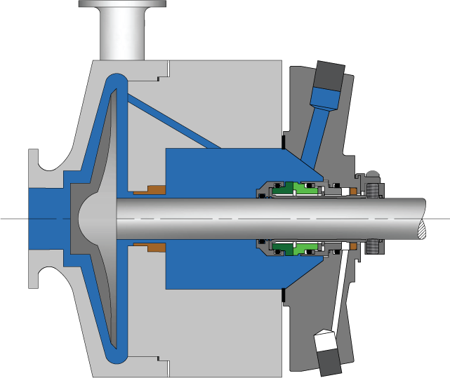
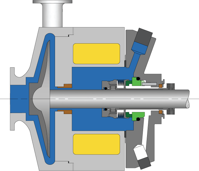
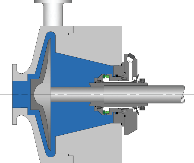
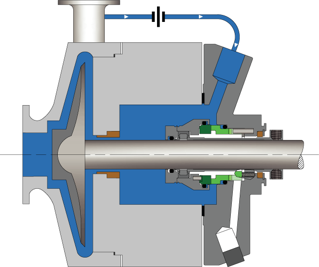
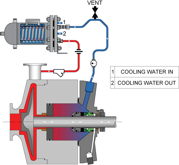
To keep mechanical seal systems functioning as long as possible, we recommend using standardized seal piping plans. Detailed API seal piping plans ensure minimal seal face wear by maintaining the optimal seal chamber environment.
This article covers best practices in seal piping installation, and outlines API standards for mechanical seal support systems.
Jump to Section
Seal Piping Installation Best Practices
To ensure the smooth operation of a mechanical seal, the installation of seal piping should follow certain guidelines.
Tubing vs. Pipe and Minimum Size Recommendations
The plumbing to and from the mechanical seal support system can be accomplished with tubing or pipe. This decision will be based on user preferences and, in some cases, the service conditions and location. Tubing is generally preferred as it is easy to remove and reinstall as well as having a very high service pressure.
Per API 682 4th Edition, tubing shall be a minimum of ½” for up to 2.5” (60mm) shaft sizes and ¾” for shafts larger than 2.5”.
Tubing wall thickness is based on the process pressures and per API 682 guidelines.
Minimize Friction Loss
Reducing the friction loses in flush piping can be achieved by:
- Using extended radius bends
- Increasing tubing size when possible
- Limiting tubing / piping runs to 16 ft or less.
These simple strategies will protect the seal and keep the seal system functional for a longer period of time.
Seal Thread Preferences
Process threads should always be lubricated with a thread compound paste rather than Teflon tape. Tape fibers can potentially be ingested into the mechanical seal or even completely block the flush flow.
Seal Elbow Selection
The use of 45 ° elbows are preferable to acute 90 ° variants and help achieve a more laminar flow within the seal, protecting it from damage.
Insulation of Hot Lines
As a rule, personnel safety should always remain a priority. Properly insulating hotlines will guarantee a higher level of safety for workers while operating around equipment requiring mechanical seals.
API Plans for Mechanical Seals
Since they were first formulated, seal piping plans have been maintained and remodeled by the American Petroleum Institute (API). Current plans are based on API 682 and are sorted numerically. In some cases, designated letters are also used to differentiate between plans.
Single Seal Piping Plans
Piping plans for single seal systems include Plans 01, 02, 03, 11, 13, 14, 21, 23, 31, 32, and 41.
Plan 01
This plan is suited to applications where process fluids could easily thicken or freeze within the piping. Plan 01 permits fluid circulation from the discharge area to the seal chamber.
Pros:
- Works like Plan 11 without the need for external piping
- Improves seal pressure and vents seal chamber when horizontal pumps are flooded
Cons:
- Lacks self-venting capability in vertical pumps
- Clean fluids are required for operation
- Flush may bypass seal face
Plan 02
Plan 02 is used in the chemical industry and other applications where low speeds and pressures are required.
Pros:
- External piping is not necessary
- Seal plan does not alter pump efficiency
- Solids are prevented from re-entering seal area
Cons:
- High temperatures may damage seal
- Not compatible with vertical pumps
Plan 03
Seal flush Plan 03 is used in applications where collection of solids within the seal chamber is anticipated. Commonly referred to as a “taper bored” seal chamber, the seal chamber shape creates a velocity profile that expels solids and circulates cool fluid to the seal.
Pros:
- Maintenance of cool seal environment without the need for external piping
- Works well with horizontal pumps
- Zero throat bushing
Cons:
- Limited control over the seal chamber environment
- Might be unsuitable for high pressure applications
Plan 11
This is the default seal plan for all Arrangement 1 and 2 seals.
Pros:
- Will provide adequate cooling for seals
- Effective air or vapor venting in horizontal pumps
- Useful as a general duties plan
Cons:
- Using polymerizing fluids with this seal plan will lead to clogging of the orifice and pumps
- Not suitable for use with fluids that might freeze or thicken within external piping
Plan 12
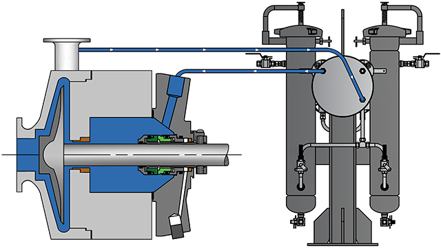
Similar to a Plan 11 with the addition of a filtration system to clean the flush liquid.
Pros:
- Dramatic seal life enhancement with proper design and operation
- Renewable filters to ensure continuous supply of clean flush liquids
Cons:
- Relatively complex system to install and maintain
- High filter change rates with extremely dirty process fluids
- Not suitable for use with fluids that might freeze or thicken within external piping
Plan 13
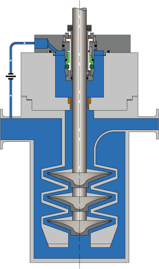
Plan 13 operation is by recirculation of fluids from the seal chamber to the pump’s suction.
Pros:
- Provides venting for air and vapors within vertical pumps
- Useful as a general duties seal plan
- Provides efficient seal cooling
Cons:
- Using polymerizing fluids with this seal plan will lead to clogging of the orifice and pumps
- Not suitable for use with fluids that might freeze or thicken within external piping
Plan 14
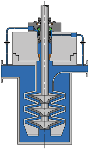
This plan is a combination of Plan 11 and Plan 13 where process fluid is recirculated from the pump discharge through a control orifice, and from the seal chamber through a flow control orifice to the pump suction.
Pros:
- Optimizes cooling and seal chamber venting
- Flush is targeted directly at seal faces
- Might help to raise seal chamber pressure and control product flashing
Cons:
- Multi-point flush injections are not recommended
Plan 21
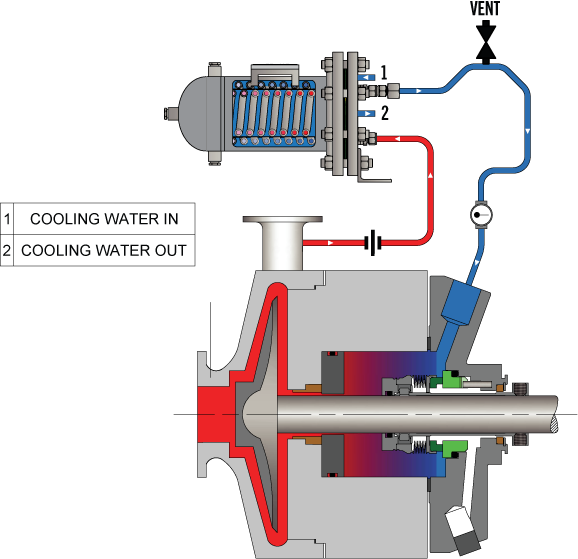
- Plan 21 is like Plan 11 but with the addition of a mechanical seal cooling system
Pros:
- Same as for Plan 11
- Cool flush improves seal lubricity and reduces coking
Cons:
- Clogging risk with elevated temperatures
- Higher energy usage
- Maintenance of the Seal Cooler
Plan 23
This plan involves the forced circulation of process fluids from the seal chamber through a seal flush heat exchanger and back to the seal chamber.
Pros:
- Improved energy savings compared to Plan 21
- Cool flush improves seal lubricity and reduces coking
Cons:
- The use of products with a high viscosity can negatively affect fluid circulation
- Maintenance of the Seal Cooler although better than Plan 21
Plan 31
API Seal Plan 31 is like Plan 11 with a bypass from pump discharge via cyclone separator.
Pros:
- Easy elimination of solid particles
- Cyclone separator facilitates clean flush
Cons:
- Constant maintenance checks for cyclone separators required
- Non-self-venting
Plan 32
Satisfactory plan for use in achieving a clean and cool environment. Requires the injection of clean fluid from an external source.
Pros:
- Improved cooling, lubricity and cleanliness of process fluids
Cons:
- Higher energy requirements
Plan 41
This is a combination of Plan 21 and Plan 31.
Pros and Cons:
- Same as for Plan 21 and Plan 31
Dual Seal Piping Plans
The best piping plans for dual seal systems include API Plans 52, 53A, 53B, 53C, 54, and 55.
Plan 52
This plan is used in Arrangement 2 seals and requires the use of an unpressurized external pump seal pot and forced circulation via a pumping ring.
Pros:
- No process fluid contamination
- Near-zero process emissions
- Integral cooling system
Cons:
- Buffer fluid is easily contaminated over time
- Requires strict adherence to best piping practices
- Seal pot maintenance high with process fluids that solidify
Plan 53A
This plan is used in Arrangement 3 seals and requires the use of a pressurized barrier fluid seal reservoir and forced circulation via a pumping ring.
Pros:
- No process fluid leaks
- Integral cooling system
Cons:
- Barrier fluids might undergo gas entrapment
- Requires strict adherence to best piping practices
- Barrier fluid levels must be maintained
- Barrier fluid and process fluids must be compatible due to the possibility of mixing
Plan 53B
Plan 53B requires the use of an extraneous barrier fluid system pressurized by a bladder accumulator delivering clean fluid to the seal faces.
Pros:
- Bladder accumulator keeps pressurized gas and barrier liquids from meeting each other
- No risk of process fluid leakage
- Heat exchanger maintains optimal process temperatures
Cons:
- Regular maintenance is required
- Requires strict adherence to best piping practices
- Barrier fluid and process fluids must be compatible due to the possibility of mixing
Plan 53C
This plan works using an extraneous barrier fluid system that is pressurized by a piston accumulator supplying clean fluid to both inboard and onboard seal faces.
Pros:
- Piston system provides continuous positive pressure differential between barrier fluid and seal faces
- Heat exchanger efficiently removes generated heat
Cons:
- Process fluids containing solids may accumulate on metal surfaces
- Regular maintenance is required
- Barrier fluid and process fluids must be compatible due to the possibility of mixing
Plan 54
Plan 54 involves the circulation of clean pressurized barrier fluid sourced from an external system. It is used in Arrangement 3 seals where barrier liquid pressures should remain at 20 psi or higher.
Pros:
- Provision of pressurized flow to multiple seals within one system
- No risk of process fluid leakage at proper system pressures
- Barrier fluids provide superior cooling
Cons:
- Barrier fluid and process fluids must be compatible due to the possibility of mixing
- Complex system with higher maintenance
Quench Seal Plans
Per the API, Plans 62, 65A, 65B, 66A, and 66B are appropriate quench seal plans.
Plan 62
This plan can be used to enhance the environment on the exposed side of single seals by quenching using steam.
Pros:
- Provides a low-cost substitute for tandem seals
- Quenching prevents coking and offers some degree of cooling
- Effective in both vertical and horizontal pumps
Cons:
- Leakage will lead to loss of pumped fluid to the exterior
Plan 65A
This is an atmospheric loss recovery plan requiring a detection and collection system for condensing leakage. Seal failure is determined by recording an excessive flow into the collection system.
Pros:
- Easy detection of seal failure by measuring leakage levels
- Low cost
Cons:
- Low leakage rates might not trigger alarms despite seal damage
- High leakage rates may result in process fluid escape to environment
Plan 65B
This is an atmospheric loss collection and detection system like Plan 65A. However, seal failure is detected by a cumulative leakage into the collection unit.
Pros:
- Like Plan 65A
Cons:
- Low leakage rates might not trigger alarms despite seal damage
- Normal levels of leakage will trigger alarms given time due to their cumulative effect
Plan 66A
This plan incorporates throttle bushings in the seal glands that reduce leaking and also enables rapid detection of seal failure.
Pros:
- Drain cavity pressure can be used to monitor seal performance
Cons:
- The use of inappropriate process fluids may cause obstructions at inner bushings
Plan 66B
This plan is intended for use in Arrangement 1 seals where limiting leakage is critical to preventing seal failure. Plan 66B uses an outlet orifice plug in its drain port to limit seal leakage and detect seal failures.
Pros & Cons:
- Same as for Plan 66A
Gas Seal Piping Plans
Gas seal piping plans include Plans 72, 74, 75 and 76.
Plan 72
This plan uses an externally supplied, low-pressure buffer gas (usually nitrogen) that is injected into the outer seal cavity. The injection process is regulated by a control panel for optimal results.
Pros:
- Reduction in fugitive emissions due to the buffer effect of nitrogen
- Prevention of icing in cryogenic applications
- This plan provides some cooling at the outboard seal
Cons:
- Loss of buffer gas will cause a rise in emissions
Plan 74
Plan 74 uses a buffer gas such as nitrogen in a dual seal system regulated by a control panel which allows the removal of moisture, gas filtration and barrier pressure regulation.
Pros:
- Low installation and maintenance costs
- Better safety profile as buffer gas leakage is inert
Cons:
- Discouraged in applications using polymerizing agents
Plan 75
This is a collection system integrating secondary containment seals for process fluids that condense at low temperatures.
Pros:
- Integrated pressure instruments detect pressure build-up indicating seal leakage or failure
Cons:
- Requires operators to manually monitor and drain leak collectors as needed
- Normal condensing leakage might trigger false alarms
Plan 76
Plan 76 seal monitoring systems divert non-condensing leakage from primary seals to a flare or vapor recovery system.
Pros:
- Low installation and maintenance costs
- Safe containment and venting of inner seal leakages
Cons:
- Accumulation of liquid within the seal chamber will generate heat and damage seal system
- Some primary seal leakage may escape into the atmosphere
Let Flexaseal Extend the Lifetime of Your Mechanical Seals
Flexaseal Engineered Seals and Systems, LLC is dedicated to providing all clients with the best mechanical seal support systems available.
Contact us online today for a quote or to learn more about the services and products we offer.