API Plan 65A
Atmospheric leakage collection and detection system for condensing leakage. Seal failure is detected by an excessive flow rate into the leakage collection system.
Description
This is an atmospheric loss recovery plan requiring a detection and collection system for condensing leakage. Seal failure is determined by recording an excessive flow into the collection system.
Application Notes
- Normally used with Arrangement 1 seals in services where seal leakage is expected to be mostly liquid.
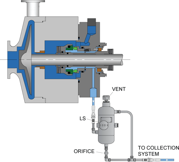
- Leakage is directed from the drain connection in the seal gland past or through a reservoir and then through an orifice, exiting into a liquid collection system.
- Valve below the gland must always remain open during pump operation to allow leakage to flow to the reservoir.
- The orifice, typically 0.20 in. [5 mm], should be located in a vertical piping leg to avoid accumulation of fluid in the drain piping.
- If flow rates are too high, the orifice will restrict the flow and the level transmitter will trigger an alarm.
- Reservoir typically includes a level transmitter and a local level indicator to monitor conditions.
- Reservoir must be mounted below the seal gland to allow leakage to readily flow to the reservoir.
- Provides an indication of excessive seal leakage and seal failure without manual inspection.
Pros:
- Easy detection of seal failure by measuring leakage levels
- Low cost
Cons:
- Low leakage rates might not trigger alarms despite seal damage
- High leakage rates may result in process fluid escape to environment