Many U.S. oil refineries use large volumes of highly concentrated hydrofluoric (HF) acid as chemical catalysts in a process called alkylation which creates additives that boost the octane of gasoline. Hydrofluoric (HF) acid is commonly found in oil refineries’ alkylation process units and is extremely corrosive and dangerous.
If released in the atmosphere, HF acid rapidly forms dense vapor clouds that hover near land and can travel great distances. Hydrofluoric (HF) acid can cause severe burns and damage the eyes, skin, nose, throat, and respiratory system. The fluoride ion is also poisonous; when entering the body through a burn or by inhalation, it can cause internal damage throughout the body. The Occupational Safety and Health Administration (OSHA) and the Environmental Protection Agency (EPA) regulate HF acid as highly toxic.
3 Mechanical Seal Arrangements for Hydrofluoric (HF) Acid Applications
The most common fluids – flashing hydrocarbons such as isobutane, propane, or alkylate fluid – are typically sealed using an API 682 Plan 32 for the primary seal flush. Because of the personnel and environmental dangers associated with exposure to HF acid, it is critical that oil refineries use the correct materials of construction in any mechanical seal designed for this chemical. Here are the accepted materials of mechanical seal construction:
- Chemically-resistant carbon grades, and alpha-sintered silicon carbide are the necessary choice for seal faces. Volatility and pressure of the hydrofluoric (HF) acid process require specific carbon grades which must be evaluated for chemical compatibility and durability in the application.
- Perfluoroelastomers are used for the secondary sealing element.
- High alloy metals with higher corrosion resistance are the primary metallurgy used for glands, collars, and other metal seal components. Historically, Monel® Alloy 400 has been used in many HF acid applications.
Single seal configurations are not recommended due to this application’s severe personnel and environmental hazards. Here are 3 mechanical seal arrangements to consider when handling hazards associated with Hydrofluoric (HF) acid applications.
1. Dual Unpressurized Seal Configuration – Wet Containment
The primary seal (inboard) seals the process fluid in the seal chamber and sees higher differential pressure. Because of the seal design and the severity of the application, it is recommended to have an API 682 Plan 32 with isobutane, propane, or alkylate flush into the seal chamber for the primary seal.
The secondary seal (outboard) seals the buffer fluid with very little differential pressure between the seal faces and atmosphere. The secondary seal in this arrangement is supported by an API 682 Plan 52 which is an external reservoir providing buffer fluid. The mechanical seal design includes an internal pumping ring to create flow and cooling to the secondary seal.
The seal support system reservoir and the secondary seal must be designed for HF acid properties and the full pressure that may be seen in the seal chamber. In this arrangement, the buffer fluid may become contaminated over time from the primary seal leakage if the inboard API 682 Plan 32 is not working properly. Once the buffer fluid is contaminated, it must be replaced and disposed of which requires maintenance intervention and the potential for personnel exposure to HF acid-containing material.
2. Dual Unpressurized Seal Configuration – Dry Contacting Containment
The dual unpressurized dry-contacting secondary seal design is not recommended for this application because of its inability to monitor the condition of the secondary seal and the severe conditions of this product. If this configuration is used, the primary seal will require the API 682 Plan 32 to keep the hydrofluoric (HF) acid away from the seal and keep the seal faces operating in a cool environment. However, just like with the unpressurized wet containment seal option, the primary seal will leak over time. So, it is critical to have confidence in the secondary seal’s ability to seal and perform effectively and safely.
Seal Support Systems for Dual Unpressurized Seals
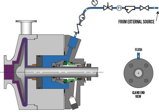
API 682 Plan 32: Clean fluid is injected into the seal chamber from an external source.
|
Advantages |
Disadvantages |
|
Provides the seal with a cool, clean lubricating fluid. |
The flush fluid must be compatible with the product stream. |
|
|
High cost. |
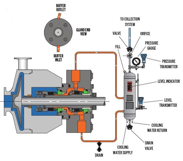
API 682 Plan 52: External buffer liquid reservoir supplying clean cool fluid to the secondary seal.
|
Advantages |
Disadvantages |
|
No process fluid contamination |
The buffer liquid will become contaminated over time |
|
Provides redundancy during a seal failure |
Best piping practices must be followed to avoid vapor lock |
|
Near zero process emissions |
|
3. Dual Pressurized Seal Configuration
Dual pressurized seal configurations utilize two sets of seal faces when the area between these two sets of faces is at a higher pressure than the process fluid within the seal chamber. In this seal design, both sets of seal faces are lubricated by the barrier fluid.
Dual pressurized seals have an advantage in hydrofluoric (HF) acid and other hazardous applications. Primarily, in the event of a mechanical seal failure, this design will keep the hazardous material within the pump and not released into the atmosphere. The second advantage is that the seal’s operation uses barrier fluid to seal on the primary and secondary seal faces and is not relying on a poor lubricating or hazardous material for face lubrication.
Dual pressurized seals can be arranged in multiple configurations. A key factor in configuration is the amount of space the pump and seal chamber allows for the seal. Another factor impacting the seal design is the pressures that must be maintained both between the seal faces as well as the seal chamber.
Seal Support Systems for Dual Pressurized Seals
Even with a dual pressurized seal, the addition of an external API 682 Plan 32 is recommended to remove or reduce the amount of HF acid in the seal chamber and around the primary seal. Typical dual pressurized seal support systems for HF acid services are API 682 Plans 53A, B, C, or Plan 54. Plans 53A, B, and C are designed to support one dual seal per system. The API 682 Plan 54 advantage is that one system can be designed to support all the hydrofluoric acid pumps within an oil refinery’s alkylation process unit.
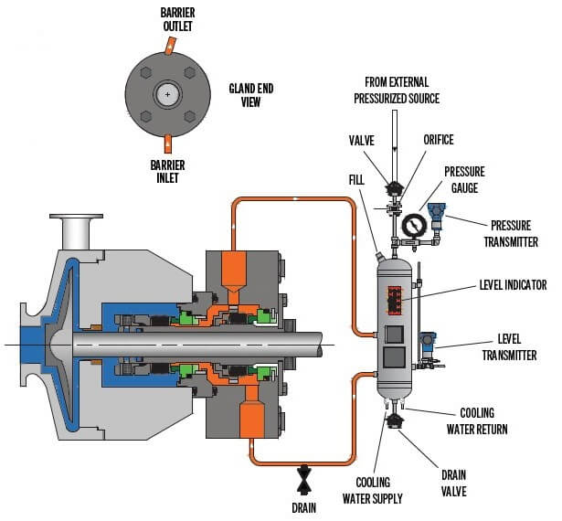
API 682 Plan 53A: Pressurized external buffer liquid reservoir supplying clean cool fluid to the primary and secondary seal.
|
Advantages |
Disadvantages |
|
No process fluid to atmosphere |
The barrier liquid must be compatible with process liquid |
|
Provides redundancy during a seal failure |
Barrier liquid can be subject to gas entrainment |
|
No contamination of the barrier fluid |
Best piping practices must be followed to avoid vapor lock |
|
Zero process emissions |
|
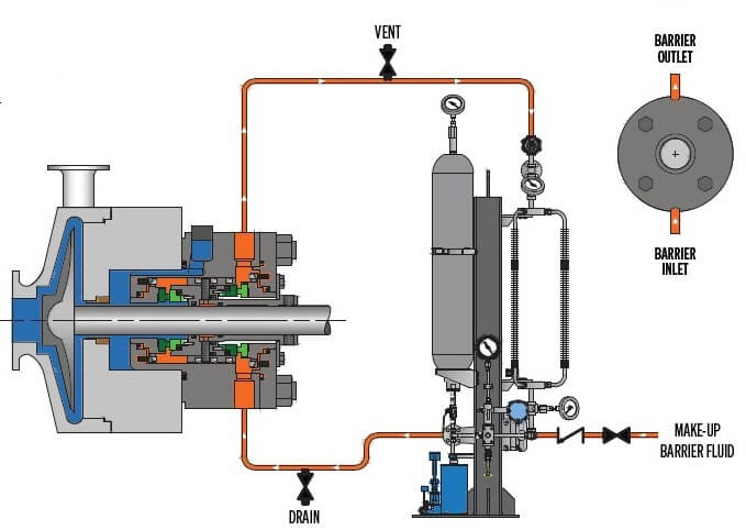
API 682 Plan 53B: Pressurized by bladder accumulator external buffer liquid reservoir supplying clean cool fluid to the primary and secondary seal.
|
Advantages |
Disadvantages |
|
No process fluid to atmosphere |
The barrier liquid must be compatible with process liquid |
|
Provides redundancy during a seal failure |
System can be costly |
|
No contamination of the barrier fluid |
Best piping practices must be followed to avoid vapor lock |
|
Zero process emissions |
|
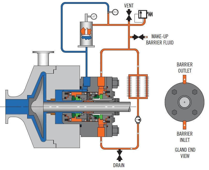
API 682 Plan 53C: Pressurized external barrier liquid system to supply clean cool fluid to the primary and secondary seal.
|
Advantages |
Disadvantages |
|
Can provide pressurized flow to multiple seal installations |
The barrier liquid must be compatible with process liquid |
|
No process fluid to atmosphere |
System can be costly |
|
Provides redundancy during a seal failure |
|
|
No contamination of the barrier fluid |
|
|
Zero process emissions |
|
|
Piston accumulator allows the system to always have a positive pressure differential |
|
|
No gas entrainment of the barrier liquid |
|
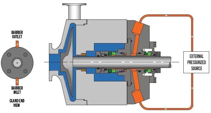
API 682 Plan 54: Pressurized external barrier liquid system to supply clean cool fluid to the primary and secondary seal.
|
Advantages |
Disadvantages |
|
Can provide pressurized flow to multiple seal installations. |
The barrier liquid must be compatible with process liquid. |
|
No process fluid to atmosphere. |
Contamination of the system can occur |
|
Provides redundancy during a seal failure. |
System can be costly |
|
No contamination of the barrier fluid. |
|
|
Zero process emissions |
|
Choosing the Right Mechanical Seal Arrangement for Your Hydrofluoric (HF) Acid Application
The toxicity, corrosiveness, and dangers of hydrofluoric (HF) acid pose significant sealing challenges. It is essential that the correct mechanical seal is chosen and professionally installed to prevent hydrofluoric (HF) acid from injuring personnel, harming the surrounding environment, and causing significant mechanical downtime that results in huge economic losses.
Choosing the right mechanical seal arrangement for your hydrofluoric (HF) application can be a difficult choice. Flexaseal Engineered Seals and Systems understands a chemical as lethal as HF acid demands the most effective sealing systems to protect your personnel and oil refinery environment. Our experienced engineers are ready 24/7 to offer guidance and support, ensuring you select the best reliable option for your hydrofluoric (HF) acid sealing challenge.
