The benefits of reducing fluid temperatures in pump-seal operation include reduced vapor pressures, increased fluid viscosity, and a reduction of generated heat at the seal faces. There are two ways to achieve these benefits: either with an air-cooled or water-cooled heat exchanger system. Both systems are effective, however there are significant differences which affect selecting the right option for your specific sealing situation. There are a few different types of water-cooled heat exchangers, each having their own pros and cons for the various applications/industries they’re used in.
The three main water-cooled heat exchangers currently available to choose from include:
- Shell and tube – used in the largest range of applications
- Spiral (tubular type) – typically used in low-volume/high pressure applications
- Plate style – most compact design
For the purposes of this article, we will focus on the shell and tube style due to its popularity throughout various industrial markets.
Overview: Shell and Tube Water-Cooled Heat Exchanger
The basic principle of the shell and tube heat exchanger is the hot fluid is circulated out of the seal chamber via metal tubing up through a housing (shell) where a second, cooler fluid – typically water or water-glycol mix – is circulated. This process cools the hot fluid within the tubing and the now-cooled fluid is returned into the seal chamber.
Connecting the seal’s gland ports to and from the heat exchanger requires the use of tubing. The tubing’s composition and material must be compatible with the hot fluid’s properties as well as adhere to any specific standards or codes set by the application or facility. It is also important to note that the tubing size should align with the exchanger’s coil diameter for optimum flow. As seen in Fig.1 below, a vent must be positioned at the high point of the system to allow for the release of any trapped gas within the seal chamber.
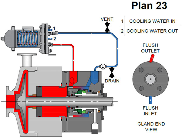
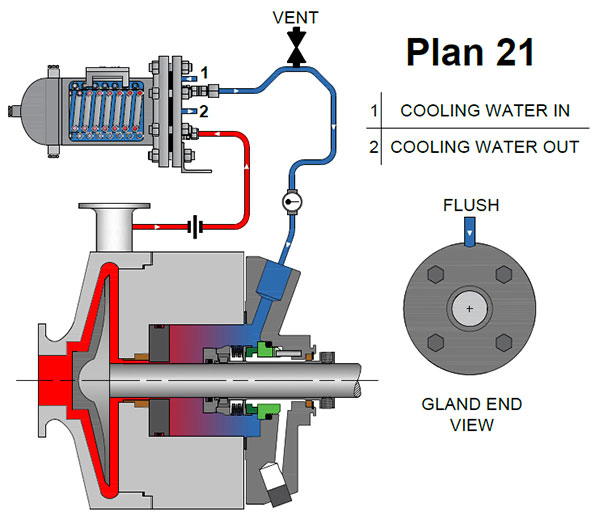
Both the API 682 Plans 21 and 23 include a close clearance throat bushing to isolate product in the seal chamber from the product in the volute. This bushing may be fixed or if a tighter clearance is necessary, a floating bushing design may be used.
Another important consideration is where the water cooled heat exchanger is positioned in relation to the seal chamber. A complex tubing design with tight angles, and right angle fittings will have a significant, adverse effect on any water cooled system by inhibiting the flow of cooling media. In Fig. 2, note the tubing’s longer, less constrictive angles which encourage optimal cooling flow. Installing the cooling unit above – but not directly on – the seal chamber will also support passive heat exchange (thermosyphoning) during operation.
Determining the Right Heat Exchanger for Your Specific Sealing Solution
Water cooled heat exchangers are a popular option to remove heat from a pumping process. However, it is critical to evaluate the following questions to determine if a water cooled exchanger is the right solution for your application.
- Does the process fluid become too viscous or prone to clogging when the temperature is reduced?
- Is the cooler’s heat load consistently high?
- Is the cooling water full of dissolved minerals?
- Is there a possibility the process fluid may boil off gases and cause a vapor lock in the system?
If the answer to any one of these is “Yes”, you may find an air-cooled heat exchanger is the better alternative. We will address air-cooled designs and configurations in our next blog article.