When dual pressurized seal applications exceed an API 682 Plan 53’s normal operating conditions for flow, pressure, and temperature, an API 682 Plan 54 seal support system is required. Equipped with external positive displacement gear pumps, the Plan 54 is designed for either a single pump or multiple pump applications on one system versus a Plan 53’s “one system per seal” configuration.
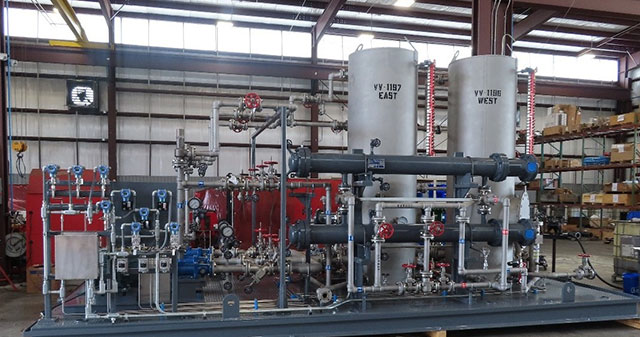
Design Overview for API 682 Plan 54
Engineering a Plan 54 seal support system for either a single seal or multiple seal applications requires specific information such as known flow, heat load, and seal chamber pressure parameters. In either situation, the flow is designed to travel from an atmospheric tank through a lubricator gear pump out to the equipment being served on a supply line. The flow then returns through a back pressure control valve to the heat exchanger and cooled barrier fluid, then moves downstream through a filter before re-entering the reservoir to complete the circulation loop.

In a multiple seal configuration where stuffing box pressures are similar, barrier fluid flow is split to each piece of equipment via a drilled orifice upstream of each mechanical seal. The orifice size is determined by proximity to each of the main pumps and is drilled accordingly to ensure an equalized flow. Typically, variable area flowmeters are provided downstream of each seal to measure flow and an orifice may be removed from circulation if it is not required to achieve the necessary flow.
When a main pump’s stuffing box pressure varies, a Kates flow control valve (instead of a flow orifice) installed upstream of each seal will provide metered flow to each seal. The return header will have a dedicated back pressure control valve for each stuffing box’s pressure.
When multiple pumps are connected to a single API 682 Plan 54 seal support system and one or more of the system’s pumps are out of service, a spillback control valve is used to divert excess flow back to the tank. As the equipment is taken offline, the overall pressure in the system will rise with the increased flow until it reaches the pressure setting of the spillback control valve. At this point, the extra flow is diverted back to the reservoir – typically by way of the heat exchanger on lubricator return to alleviate any accumulated heat generation. The spillback control valve’s pressure setting is set between the pump protection valve and back pressure control valve: both back pressure control and spillback control valves may be supplied as either digital or mechanical units depending on customer preference.
Digital valve technology simplifies operation and uses trending data to isolate and indicate mechanical seal leakage. A Plan 54 seal support system utilizing digital valve technology can service fifteen or more multi-pump applications while providing important preventative maintenance measures during day-to-day operations, ensuring system longevity. The right standardized seal piping plan keeps mechanical seal systems functioning as long as possible.
Extend the Lifetime of Your Mechanical Seals with API 682 Plan 54
Having trouble choosing the right seal support system for your application? No matter the environment – whether liquid or gas, extreme temperatures, abrasives, or other volatile conditions, Flexaseal Engineered Seals and Systems has the engineering expertise to help you select the best option for your sealing challenge, ensuring mechanical seal reliability and longevity.
