The mating pair of counter-rotating seal rings are the heart of the mechanical seal and designers must consider many overlapping physical systems affecting their performance. Sealing systems are complex, and the influence of each physical system is typically on the same scale:
- Tribological
- Mechanical
- Thermodynamic
- Fluid dynamic
There are also the rare cases where the seal is subject to electrical and radioactive effects, but these are not considered in this brief post.
Considerations for Mechanical Seal Ring Design
There are many factors to consider when designing a resilient mechanical seal ring. This article will look specifically at how mechanical loads, thermal loads, and seal ring deformation all impact a success mechanical seal design.
Mechanical Loads
Designing for resilience starts with determining the loads applied to the mechanical seal rings. Mechanical loads are exerted by other components and by the surrounding fluid pressure.
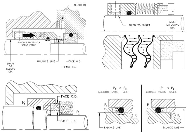
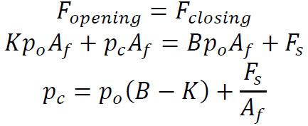
To maintain the required static equilibrium, fluid pressure and spring force applied on the rear of the seal ring is supported on the other end by a mix of fluid film pressure and contact between the two seal faces. Fluid pressure applied on the front and rear faces of the seal ring exerts axial forces that will either open or close the seal faces against each other. Most of the pressure gets “canceled out” (is acting equally on both sides), what matters are the boundaries on either side of the seal ring where pressure is being sealed.
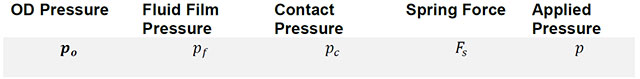
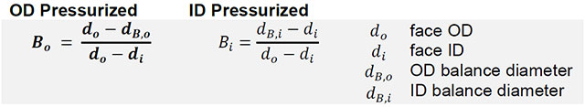
On the front that’s defined by the sealing face (opening area) and in the rear by the secondary sealing diameter, dubbed the balance diameter (closing area). The ratio of closing area to opening area is the seal balance, B, and is also often expressed as a percentage. It represents the fraction of fluid pressure acting to close the seal. To simplify, we take the OD pressure to be the gauge pressure so the ID pressure is zero.

Seal designs are considered unbalanced or balanced. Unbalanced seals have a greater closing area than the seal face (B > 1) and apply more load to the faces than is necessary. Unbalanced seals are simple in design and cheap to manufacture. Balanced seals have a closing area smaller than the seal face—a well designed seal will only apply as little closing force as required for satisfactory long-term seal performance to minimize the face contact pressure. The chart below shows, all else being equal, the big influence balance has on the contact pressure between the faces.

The balance diameter on pusher seals is set by the location of the dynamic O-ring, on non-pusher seals it depends on the device’s mean effective diameter. Edge welded metal bellows seals are inherently balanced because the loading device also seals and eliminates the need for a dynamic O-ring. The balance is determined differently depending on whether the pressure is higher on the inside or outside of the seal ring. A double balanced seal is one which is balanced when pressurized either from the inside or on the outside. Double balanced seals are applied when unsteady conditions may cause a reversal of pressure across the faces, and also on dual seals that are intended to be used universally in pressurized and non-pressurized applications.
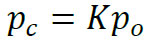
To find out exactly how light a closing force is needed requires understanding a little better how much pressure the fluid film is capable of exerting between the faces. Pressure drops continuously from the high-pressure side to the low-pressure side of the seal face, so that the average fluid pressure applied on the face is only a fraction of the total differential pressure. That portion of the total differential pressure is referred to as the pressure gradient factor, a.k.a. ‘K’ factor, and changes depending on the seal face design and type of sealed fluid.
A seal with standard flat, parallel faces and a non-flashing liquid between them has a K factor of exactly 1/2. Contacting mechanical seals get their name because the fluid film cannot support the entirety of the applied load on its own and so the remainder is supported by contact between the two face materials.
It should be clear that if the K factor is sufficiently large, the fluid film pressure will overcome the closing forces and open the seal. The following constraint is imposed:
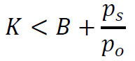
The amount of pressure the fluid film can support, K, changes—by design or otherwise. The face profile has a big effect on K and may change due to face deflections from operating loads or deliberately designed pressure amplifying features. The type of fluid, too, has an impact; gasses and flashing liquids will exert more pressure as they expand across the faces. As a result, the seal balance ratio is adjusted for light hydrocarbon applications to mitigate the risk of excessive leakage or seal face opening.
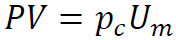
The contact pressure is an important property to determine; it is used primarily in the PV calculation to determine the applicability of a mating pair of seal face materials in an application and is the product of the contact pressure and the sliding speed.
Thermal Loads
Though viscous shear does take over as the predominant heat-generating mechanism above high viscosities and/or high surface speeds, it is material-to-material friction contact that generates the bulk of the heat load in most mechanical seal applications.
The heat generated by friction between the faces is carried away to a minimal extent by the normal liquid leakage, but mainly it is absorbed by the two seal ring materials and transferred to the surrounding fluids by convection. After settling into an equilibrium with the surrounding environment and the face heat load, a seal ring has a temperature distribution that is typically hottest on the ID of the face, cooler on the OD of the face where the fluid flow is, and coolest in the rear of the seal ring furthest away from the face.
This temperature gradient causes the seal ring to expand unevenly, resulting in distortions and internal stresses. Thermal shocks from sudden temperature increases will produce radial stress cracks that cause the seal to fail—some materials like tungsten carbide are particularly susceptible as compared to silicon carbides. Pressure and temperature caused deformations of the face profile can further increase heat generation between the faces. In the worst cases, instability could occur leading to repeated opening and closing of the faces, chipping along the edges, and seal failure.
Seal Ring Deformation
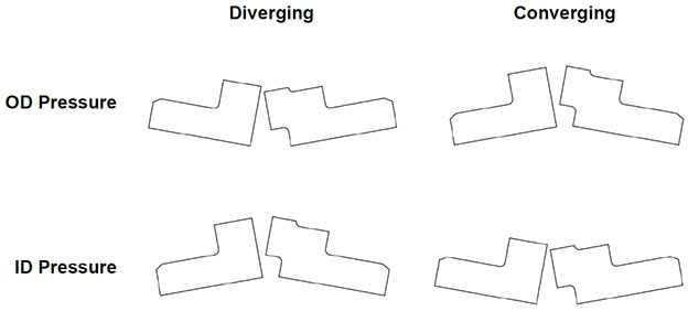
Deflections caused by mechanical and thermal loads can be roughly described as rotations of the cross-section around its centroid. Tangential loads from anti-rotation devices can also significantly flex the seal faces. If you were to greatly exaggerate the actual deformation, the cylindrical ring would look either like an expanding or reducing funnel. Care is taken when designing the seal to make as stiff a shape as possible and to ensure that when deflections happen, they are in the direction that is beneficial to the function of the mechanical seal.
If the seal section rotates so that the faces are converging on the low-pressure side, then more fluid can enter the sealing gap which increases the fluid film pressure, reduces contact, wear, and heat-generation between the faces. This is the characteristic V-gap. However, too dramatic a relative angle between the faces will increase the pressure gradient factor above the balance ratio and result in excessive leakage and seal failure.
If the seal deflects so that the faces are diverging away from the high-pressure side, then flow to the fluid film is pinched off and will collapse. Without a fluid film the mechanical seal runs dry and will certainly fail.
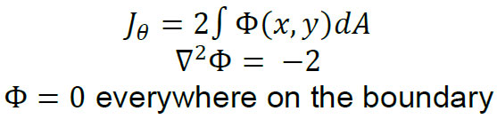
The shape of the seal ring cross-section is always constrained by available space, seal configuration and orientation—among many other things—but the designer can compare design possibilities by quantifying their stiffness/resistance to flex under load. The most useful to know is the torsional stiffness of the seal ring shape, which is not straightforward and requires solving Poisson’s equation and integrating over the section area. Using numerical methods this can be done quickly and many designs can be compared at once.
Apart from playing with the face geometry and features to reduce the heat load, the designer can also choose how to distribute the forces around a seal to minimize moments applied by the fluid pressure. One way of doing this is by using the placement of the secondary sealing element. A seal with an O-ring too close to the faces will experience a moment applied over the face, possibly far away from the section centroid, that is not balanced out on the other end of the seal ring. By adjusting the location of the centroid and the secondary sealing element, rotation of the seal ring can be minimized.
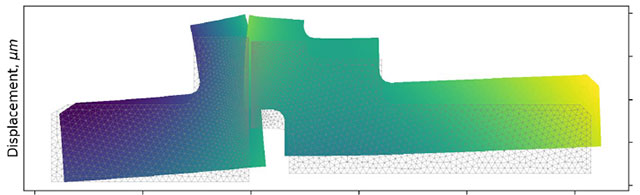
Finite Element Analysis
Many simplifications of the mechanical seal problem are required for a curved-beam analysis. In reality the seal ring does not perfectly maintain its overall form while simply being rotated around the centroid of the shape. Instead, the material is stretched more in some places than others and in differing directions. Finite element analysis helps model complex physical phenomena by projecting the physical world and its continuity onto a world where everything is made up of little triangles. Fixed conditions are applied at different boundaries and at each triangle complex physical phenomena are simplified to simple addition and subtraction. The forces and heat flux going in and out of the triangles are summed together to get a clear picture of how the seal is behaving and performing. The best models available will couple the thermo-fluidic, mechanical, and tribological systems so that there is clear feedback among the systems and the most accurate picture of seal face behavior can be illustrated.