API Piping Plans
Seal support plans and their associated systems are critical to the longevity and reliability of mechanical seals in rotating equipment. The API Seal Plans shown here are in conformance with API 682 4th edition / API 610 10th edition.
These standardized flush and support systems are widely used throughout industry. Custom variants are also possible to meet specific application conditions and requirements, so called API Plan 99 systems.
Contact Flexaseal for any of your seal support systems needs or questions at sales@flexaseal.com or by calling +1 (832) 804-7424.
Filter by Application
Filter by Plans
Filter by Application
Filter by Plans
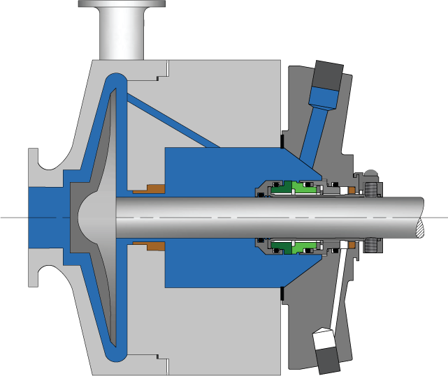
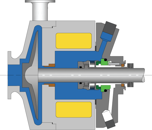
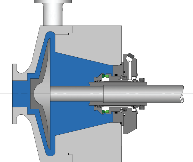
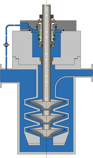
API Plan 02
Dead-ended seal chamber with no recirculation of fluid and optional cooling/heating jacket.
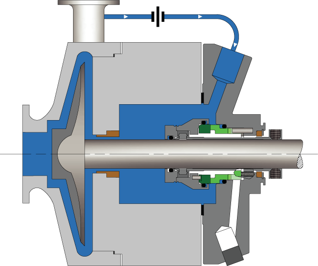
API Plan 11
Recirculation from pump discharge through a flow control orifice to the seal chamber.
API Plan 12
Recirculation from pump discharge through a strainer and flow control orifice to the seal chamber.
API Plan 13
Recirculation from the seal chamber through a flow control orifice to pump suction.
API Plan 14
Recirculation from pump discharge through a flow control orifice to the seal chamber and from the seal chamber through a flow control orifice to pump suction.
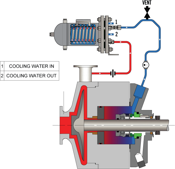
API Plan 21
Recirculation from pump discharge through a flow control orifice and cooler to the seal chamber.
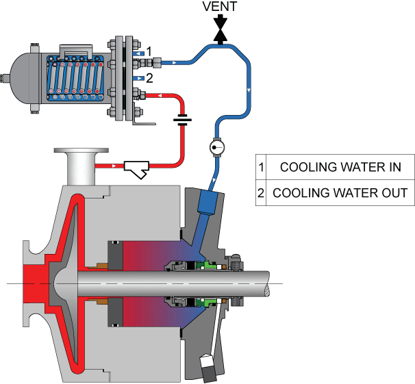
API Plan 22
Recirculation from pump discharge through a strainer, flow control orifice, and cooler to the seal chamber.
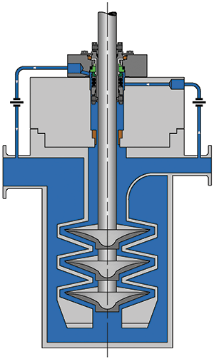
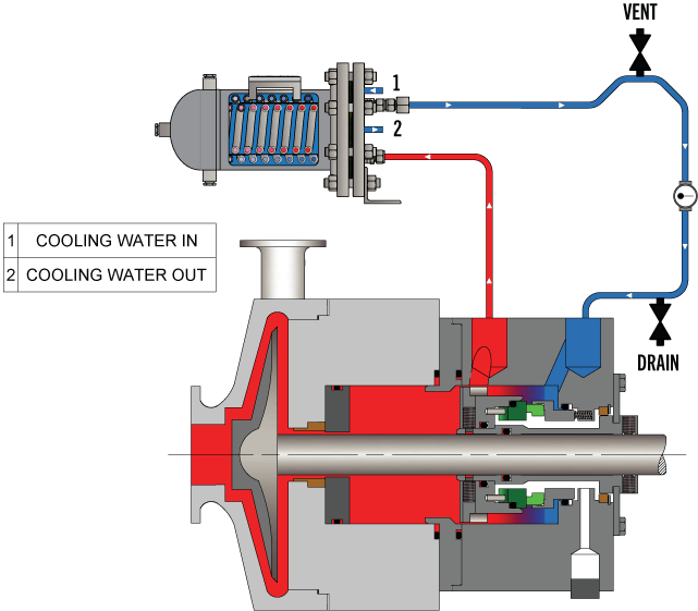
API Plan 23
Forced circulation from the seal chamber through a cooler and back to the seal chamber.
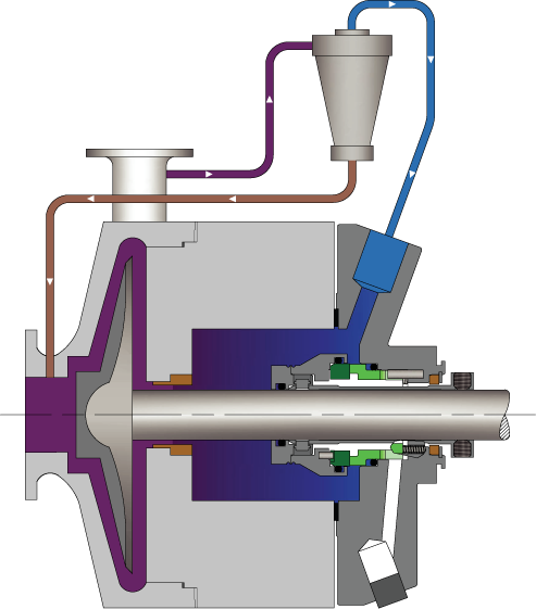
API Plan 31
Recirculation from pump discharge through a cyclone separator, delivering clean fluid to the seal chamber and solids to pump suction.
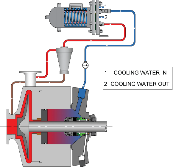
API Plan 41
Recirculation from pump discharge through a cyclone separator delivering clean fluid to a cooler and then to the seal chamber. Solids are delivered to pump suction.
API Plan 51
External reservoir providing a dead-ended fluid blanket to the quench connection.
API Plan 52
External buffer liquid reservoir supplying clean fluid to the outboard seal faces.
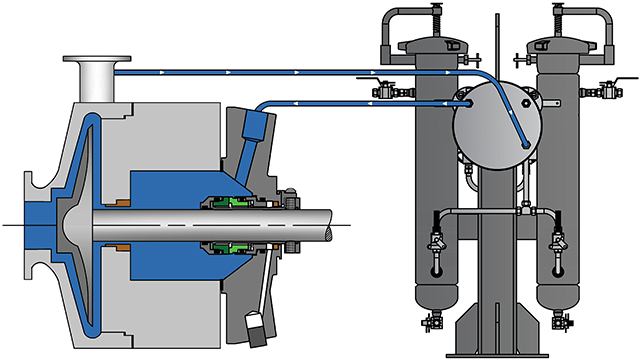
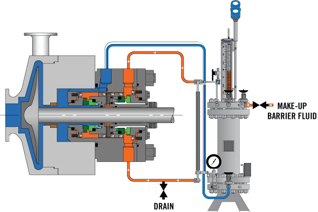
API Plan 53A
Pressurized external barrier liquid reservoir supplying clean fluid to the inboard and outboard seal faces.
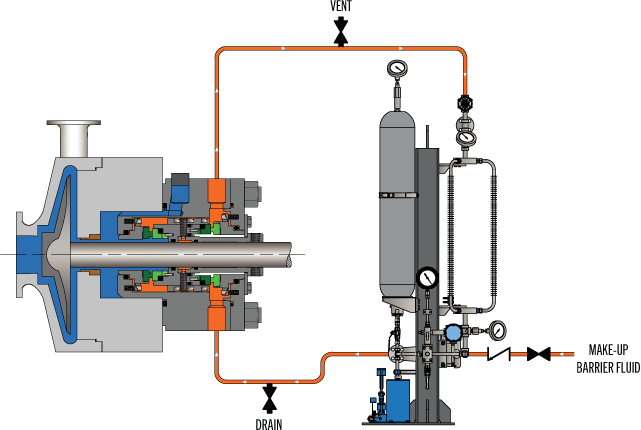
API Plan 53B
External barrier liquid system pressurized by a bladder accumulator supplying clean fluid to the inboard and outboard seal faces.
API Plan 53C
External barrier liquid system pressurized by a piston accumulator supplying clean fluid to the inboard and outboard seal faces.
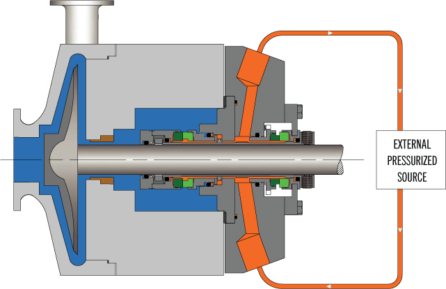
API Plan 54
Pressurized external barrier liquid system supplying clean fluid to the inboard and outboard seal faces.
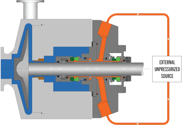
API Plan 55
Unpressurized external buffer liquid system supplying clean fluid to the inboard and outboard seal faces.
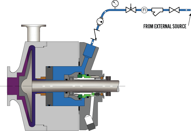
API Plan 62
Quench stream is brought from an external source to the atmospheric side of the seal.
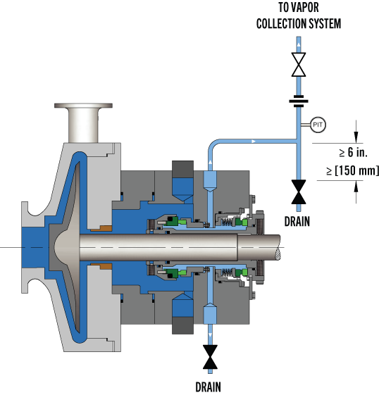
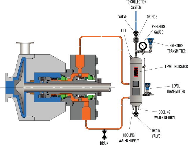
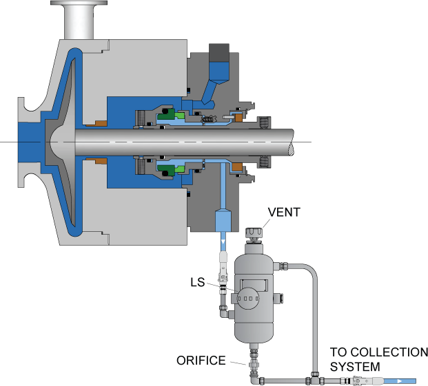
API Plan 65A
Atmospheric leakage collection and detection system for condensing leakage. Seal failure is detected by an excessive flow rate into the leakage collection system.
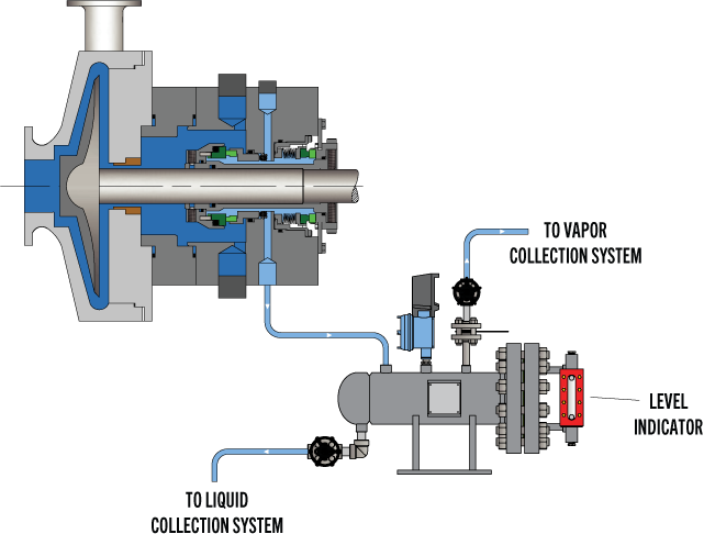
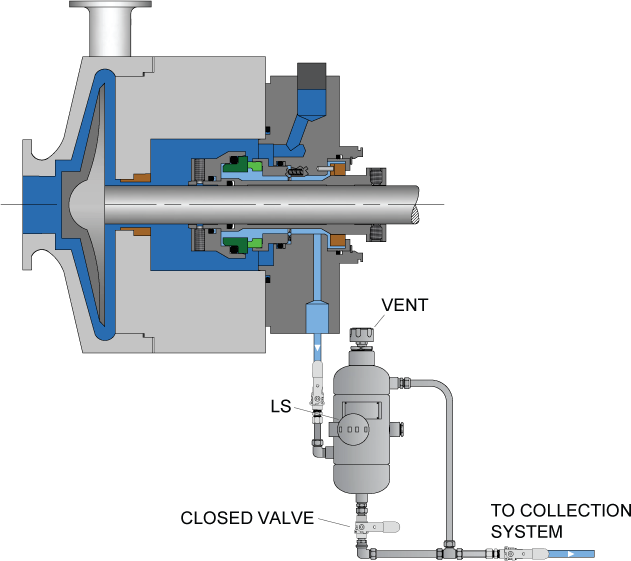
API Plan 65B
Atmospheric leakage collection and detection system for condensing leakage. Seal failure is detected by cumulative leakage into the leakage collection system.
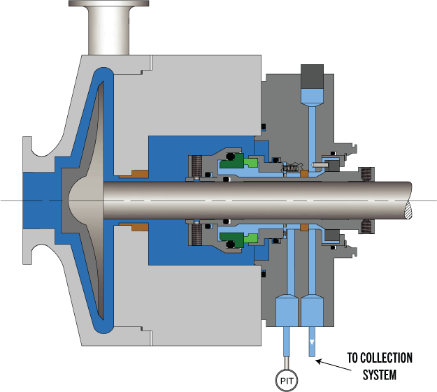
API Plan 66A
Throttle bushings in the seal gland minimize the leakage leaving the seal gland and allows for detection of a seal failure.
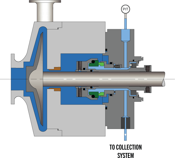
API Plan 66B
An orifice plug in the drain port minimizes the seal leakage leaving the seal gland and allows for detection of a seal failure.
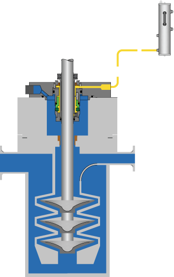
API Plan 71
Tapped connections for the purchaser’s use in the future for buffer gas applications.
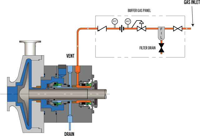
API Plan 72
Externally supplied buffer gas maintained at a pressure less than the seal chamber pressure.
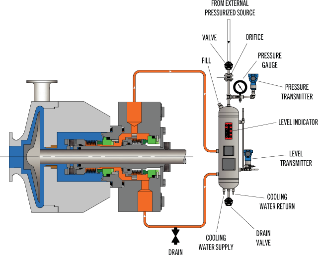
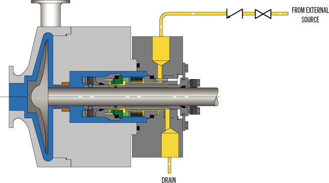
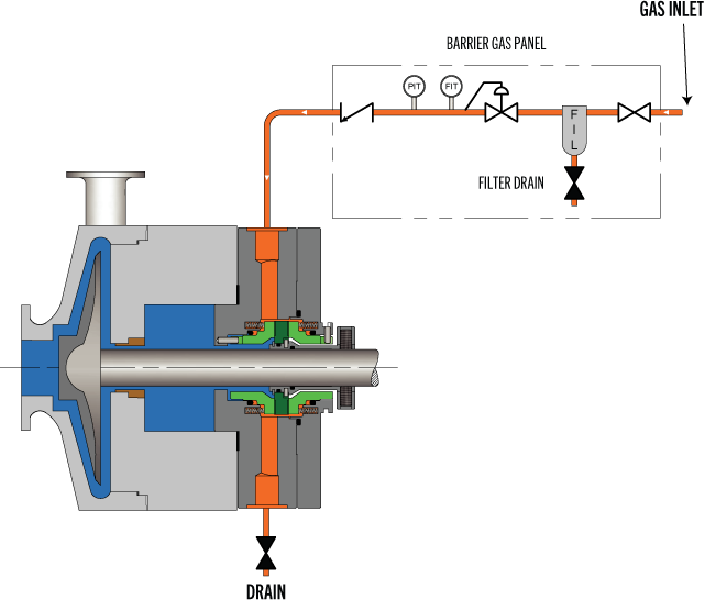
API Plan 74
Externally supplied barrier gas maintained at a pressure greater than the seal chamber pressure.
API Plan 75
Leakage collection system for condensing or mixed phase leakage with a contacting containment seal.