A mechanical seal will run at its most stable condition when there is a sufficient pressure margin in the seal chamber over the process liquid’s vapor pressure at local temperature. The vapor pressure margin is defined as the difference between the absolute pressure in the seal chamber and the absolute vapor pressure of the pumped fluid. Flashing within the fluid film at the seal faces can be a major cause of seal dry running and premature seal failure. Cooling the process liquid to lower the vapor pressure is the API 682-preferred method of raising the vapor pressure margin, however, this is not always an option for some applications.
In lieu of cooling the liquid, which can be more cost-intensive or impractical for some services, the most used piping plans are those that act to remove the seal-generated heat while further raising the seal chamber pressure to achieve the desired vapor pressure margins. API 682 4th Edition standard states that the vapor pressure margin in the seal chamber shall be a minimum of 50 psi, or a minimum ratio of 1:3 between the absolute pressure in the seal chamber and the absolute vapor pressure of the pumped fluid at the pumping temperature if the 50 psi differential cannot be met. For face-generated heat, the API 682 recommendation is to flush the seal to limit a seal chamber temperature increase to less than 10°F.
Common Mechanical Seal Piping Plans to Achieve Desired Vapor Pressure Margins
While this subject has been extensively researched and documented this condensed discussion will only consider the most common flush plans used with mechanical seals. These plans can utilize the pressure distribution within the equipment to drive flow and manipulate the conditions local to the mechanical seal; in doing so, the environment can be made more favorable to long-term seal performance.
These plans do not rely on any supporting instrumentation or devices like a heat exchanger, but rather manipulate the pump and system’s pressure distribution as a mechanism to increase the vapor pressure margin. When considering the use of a mechanical seal piping plan, it is important to understand how specific pump arrangements can impact the seal chamber (and ultimately the performance of the mechanical seal) as the pressure and flow distribution will vary depending on several factors. These factors include but are not limited to:
- Bore configuration
- Number of stages
- Balance lines
- Throttle bushings
It is important to note that an improperly selected mechanical seal piping plan can be detrimental to seal performance in the same vein that a properly selected plan can improve seal performance.
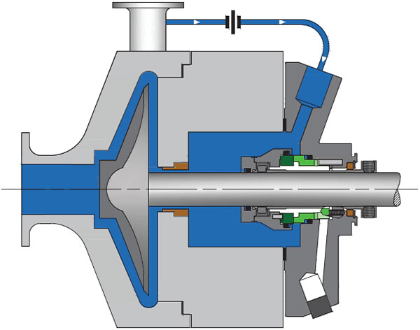
The following mechanical seal piping plans service the inboard region of the seal – the region directly exposed to the process liquid. These piping plans are often employed to support single cartridge seals and/or unpressurized double cartridge seals where the seal faces will be relying on the process liquid for lubrication.
API 682 Seal Piping Plan 11
API 682 Plan 11, often the default API Plan for most single seals, is defined by its ability to prevent vaporization by maintaining positive pressure above vapor pressure. Additional features and characteristics include:
- Vents and cools the seal environment of face-generated heat.
- Recirculation from a higher-pressure region of the pump to the seal chamber.
- Often is sourced from first-stage discharge or the crossover in horizontal multi-stage pumps.
- Throat bushing and orifice dimensions play into pressure and flow degradation to the seal chamber.
API 682 Seal Piping Plan 14
API 682 Plan 14 is a combination of Plan 11 and Plan 13 where process fluid is recirculated from the pump discharge through a control orifice, and from the seal chamber through a flow control orifice to the pump suction. Additional features and characteristics include:
- Recirculation from discharge to the seal chamber and from the seal chamber to suction.
- Allows for continuous venting and flushing of the mechanical seal.
- Throat bushing acts to further isolate the seal chamber.
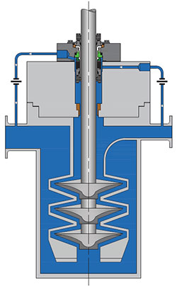
The operating premise of these two piping plans is essentially the same – connect to a higher-pressure region of the pump to raise the local seal chamber pressure and introduce a flow to sweep away seal-generated heat. Through calculations relating to orifice dimensions, throat bushing clearances, pressure differentials, and expected face-generated heat, the desired seal environment can often be constructed from previously unfavorable conditions.
The point of focus in mechanical seal and seal support system design centers around managing the conditions of the very thin fluid film that supports the seal faces and prevents atmospheric escapes. Along with broad material compatibility and design requirements, the management of this fluid film is often the center of focus when reviewing a seal application, as the conditions within the seal chamber have a direct impact on the stability and consistency the mechanical seal faces experience.
Manage Your Seal Chamber Vapor Pressure Margins with the Right Mechanical Seal Piping Plan
There are certainly other piping plans and tactics that can help to manage seal chamber vapor pressure margins or fluid film stability within the seal. For further review, Flexaseal’s Piping Plan Guide includes a comprehensive breakdown of all defined piping plans and how they can impact the sealing environment.